Floor indicators
Floor indicators from Weiss raised access floor systems
The floor indicators are hollow moulded, made of glass fabric and resin, the tread is enriched with crushed quartz to guarantee slip resistance.
Thanks to our production process, the surface is sealed and non-porous so that chewing gum, ketchup and coloured drinks leave no permanent marks, even after cleaning.
All types of guide lines for the blind vibrate in the frequency range of 550 Hz when touched by a stick, which is clearly audible even in normal traffic noise.
They are resistant to all waste water media on the road.
Description
- Slip-resistant
- Guide line
- Fields of attention
- Acoustic perception
- Highly resilient
- De-icing salt resistant
- Temperature resistant
- No water absorption
- Easy to clean
Guidance systems for the blind offer blind and visually impaired people a safe solution for everyday life. They can use the tactile information provided by the hollow floor indicators by recognising them with a long cane and/or perceiving them with their feet.
The high visual contrast enables people with visual impairments to recognise clear orientation lines and points.
With the help of a cane, people with visual impairments can move around public spaces, buildings and bus stops more safely and easily.
Guidance systems for the blind usually consist of guiding strips and attention fields. These systems can also be applied as floor coverings. The guiding strips mark the way to attention fields.
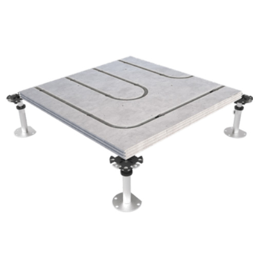
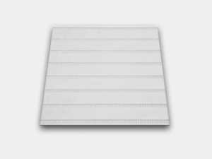 Grooved plates
Grooved plates are defined in accordance with DIN 32984 for floor indicators in public traffic areas.
The narrow grooves (sinusoidal grooves) provide good guidance with a long pole and can be felt by the soles of shoes.
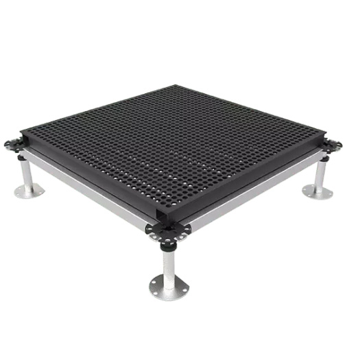
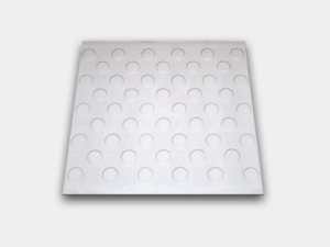 Dimpled sheets
Have been used since the mid-1990s, especially at pedestrian crossings with traffic light systems with studs.
The studs can be felt both with a long cane and with the feet.
Technical data
| Test specimen | Remaining | Deformation | Nominal test force | Breaking load | |||
| Zero measurement in mm | At 2/3 of the nominal test force in mm | Difference in mm | Visual assessment | kN | Visual assessment | kN | |
| 1 | 33,0 | 33,1 | 0,1 | No recognisable visual changes | 250 | No recognisable visual changes | 319 |
| 2 | 33,2 | 33,4 | 0,2 | No recognisable visual changes | 250 | No recognisable visual changes | 306 |
| 3 | 33,3 | 33,4 | 0,1 | No recognisable visual changes | 250 | No recognisable visual changes | 307 |
Further information
The test specimens were subjected to a compressive load in the MB 300 compression testing machine. The profiled surface of the test specimen was levelled by the client using plastic on a separating layer.
The permanent deformation was determined after five loads up to ⅔ of the test load.
Immediately afterwards, the target test load of 250 KN was applied and held for 30 seconds. The test specimen was visually assessed in this state.
After the visual assessment, the test specimen was loaded further until failure of the test specimen occurred.
The dummy guidelines are available in the formats
| HOBI I | 300 x 300 x 80 mm |
| HOBI II | 300 x 300 x 15 mm |
| HOBI I | 300 x 300 x 2,0 mm |
| Load-bearing | capacity Load class C 250 |