PEDESTALS
Pedestals from WEISS raised floor systems
All Weiss raised floor pedestals are made from galvanized, blue passivated steel. The range covers small pedestals to compensate for irregularities in hollow floor systems through to customized heavy-duty pedestals in a wide variety of lengths.
We offer our customers the entire range of sizes and variations, also in individual intermediate lengths. When laying raised access floor panels, the most commonly used pedestals are the so-called M16 and M20 pedestals.
Description
Description
- The pedestal is glued to the raw floor with PU glue. The surface must be firm, dry and resilient so that the connection is perfect and durable. A double anchorage of the pedestal is optional.
- Once the pedestal is fully fixed, the height of each pedestal can be finely adjusted and then get locked mechanically with a lock screw.
- The adjustment range for the pedestals has a range 25 mm to 2,000 mm. Special heights are possible depending on the application. Up until now, maximum heights of 5,000 mm have been realized.
- Precision, high load-bearing capacity and well thought-out details that make life easier for the fitter are the hallmarks of our pedestals.
Models
M20 (Socket pedestal)
The M20 pedestal is available in a standard version with a 24 x 2 mm leg or a heavy-duty version with a 26 x 3 mm leg.
During installation, the pedestal is inserted into the leg and then the height is adjusted with a nut.
As the M20 pedestal comes in different variants depending on the application and load requirements, it is ideally suited for use in high raised floor installations where large load-bearing capacities are required.
 M16 (Screw pedestal)
The M16 pedestal base has a 22 x 1.8 mm leg with a threaded socket, and the selected pedestal head is screwed onto the pedestal itself.
Screw pedestals are especially suited to installations with restricted heights or low load-bearing capacity, where they offer an ideal balance between economy and functionality.

 M12 (Screw pedestal)
Small base plate – large head plate for an optimal and economic installation of hollow floor systems in wet or dry version.
The M12 pedestal with a 14 x 1.1 mm leg has a threaded socket, so that the respective head can be screwed to the pedestal base.

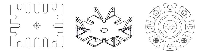
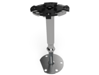
CS | DS HEAD
Weiss manufactures a unique universal head that is equally suited to carrying support stringers or C-profiles.
The CS/DS topside is designed to match the M20 socket pedestal (24 x 2 mm or 26 x 3 mm) and can be used in all common floor systems.
As the heads are universal, they can bear either raised floor panels or stringers for horizontal stiffening.
Furthermore, both C-profiles and stringers can be fastened in a variety of orientations.
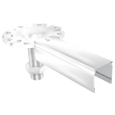
CF | DF HEAD
The CF/DF topside fits perfectly with existing edges, and is therefore often used in switch room pedestals when building the framework.
It can be used with a 24 x 2 mm or 26 x 3 mm leg. The flat head panel makes it the ideal design for creating frameworks that will carry heavy UPS systems, server racks, transformer stations, etc. All common C-profiles can be screwed onto the frame head.
If the CF/DF head is rotated laterally, it has numerous slits and screw options, while in its longitudinal configuration it fits closely with existing walls.
It can be configured for 100 mm or 120 mm as required. This makes it the perfect head for laying reserve panels or transitions in walkways and frame areas.
The CF/DF topside comes with the 120 mm bolt as standard. However, it is equally possible to use the 100 mm bolt. It is also possible to assemble up to three profiles next to each other.
CW | DW HEAD
The claw head CW/DW topside is primarily used in switch room profile systems.
The installation can use either the 24 x 2 mm pedestals or the 26 x 3 mm.
The claw head is not only ideal for laying swathes of switch gear station floors (i.e. creating walkways).
It is perfect for fitting all available C-profiles.
Technical data
M12 AS
| M12 AS Description | Adjustment range in mm | Weight approx. |
| Typ AS 2 | 35-51 | 0,18 kg |
| Typ AS 3 | 47-78 | 0,20 kg |
| Typ AS 4 | 57-98 | 0,21 kg |
| Typ AS 5 | 74-131 | 0,24 kg |
| Typ AS 6 | 107-168 | 0,26 kg |
| Typ AS 7 | 147-208 | 0,29 kg |
M16 BS
| M16 BS Description | Adjustment range in mm | Weight approx. |
| Typ BS 1 | 25-37 | 0,30 kg |
| Typ BS 2 | 35-48 | 0,32 kg |
| Typ BS 3 | 45-71 | 0,39 kg |
| Typ BS 4 | 63-94 | 0,40 kg |
| Typ BS 5 | 80-130 | 0,44 kg |
| Typ BS 6 | 120-200 | 0,51 kg |
| Typ BS 7 | 170-290 | 0,62 kg |
| Typ BS 8 | 280-400 | 0,75 kg |
| Typ BS 9 | 425-485 | 0,85 kg |
M20 CS
Typ 22 CS725 – 7851,23 kg
Rango de ajuste en mm
| M20 CS Description | Adjustment range in mm | Weight approx. |
| Typ 10 CS | 140 – 200 | 0,64 kg |
| Typ 11 CS | 175 – 235 | 0,69 kg |
| Typ 12 CS | 225 – 285 | 0,74 kg |
| Typ 13 CS | 275 – 335 | 0,79 kg |
| Typ 14 CS | 325 – 385 | 0,84 kg |
| Typ 15 CS | 375 – 435 | 0,89 kg |
| Typ 16 CS | 425 – 485 | 0,94 kg |
| Typ 17 CS | 475 – 535 | 0,98 kg |
| Typ 18 CS | 525 – 585 | 1,03 kg |
| Typ 19 CS | 575 – 635 | 1,08 kg |
| Typ 20 CS | 625 – 685 | 1,13 kg |
| Typ 21 CS | 675 – 735 | 1,18 kg |
| Typ 23 CS | 775 – 835 | 1,27 kg |
| Typ 24 CS | 825 – 885 | 1,32 kg |
| Typ 25 CS | 875 – 935 | 1,37 kg |
| Typ 26 CS | 925 – 985 | 1,42 kg |
| Typ 27 CS | 975 – 1035 | 1,47 kg |
| Typ 28 CS | 1025 – 1085 | 1,51 kg |
| Typ 29 CS | 1075 – 1135 | 1,56 kg |
| Typ 30 CS | 1125 – 1185 | 1,61 kg |
M20 DS
Typ 39 DS1575 – 16353,47 kg
| M20 DS Description | Adjustment range in mm | Weight approx. |
| Typ 20 DS | 625 – 685 | 1,68 kg |
| Typ 21 DS | 675 – 735 | 1,77 kg |
| Typ 22 DS | 725 – 785 | 1,87 kg |
| Typ 23 DS | 775 – 835 | 1,96 kg |
| Typ 24 DS | 825 – 885 | 2,05 kg |
| Typ 25 DS | 875 – 935 | 2,15 kg |
| Typ 26 DS | 925 – 985 | 2,24 kg |
| Typ 27 DS | 975 – 1035 | 2,34 kg |
| Typ 28 DS | 1025 – 1085 | 2,43 kg |
| Typ 29 DS | 1075 – 1135 | 2,52 kg |
| Typ 30 DS | 1125 – 1185 | 2,62 kg |
| Typ 31 DS | 1175 – 1235 | 2,71 kg |
| Typ 32 DS | 1225 – 1285 | 2,81 kg |
| Typ 33 DS | 1275 – 1335 | 2,90 kg |
| Typ 34 DS | 1325 – 1385 | 3,00 kg |
| Typ 35 DS | 1375 – 1435 | 3,09 kg |
| Typ 36 DS | 1425 – 1485 | 3,18 kg |
| Typ 37 DS | 1475 – 1535 | 3,28 kg |
| Typ 38 DS | 1525 – 1585 | 3,37 kg |
M20 CW
| M20 CW Description | Adjustment range in mm | Weight approx. |
| Typ 8 CW | 65 – 85 | 0,50 kg |
| Typ 9 CW | 90 – 125 | 0,55 kg |
| Typ 10 CW | 140 – 200 | 0,60 kg |
| Typ 11 CW | 175 – 235 | 0,71 kg |
| Typ 12 CW | 225 – 285 | 0,76 kg |
| Typ 13 CW | 275 – 335 | 0,81 kg |
| Typ 14 CW | 325 – 385 | 0,86 kg |
| Typ 15 CW | 375 – 435 | 0,90 kg |
| Typ 16 CW | 425 – 485 | 0,95 kg |
| Typ 17 CW | 475 – 535 | 1,00 kg |
| Typ 18 CW | 525 – 585 | 1,05 kg |
| Typ 19 CW | 575 – 635 | 1,10 kg |
| Typ 20 CW | 625 – 685 | 1,14 kg |
| Typ 21 CW | 675 – 735 | 1,19 kg |
| Typ 22 CW | 725 – 785 | 1,24 kg |
| Typ 23 CW | 775 – 835 | 1,29 kg |
| Typ 24 CW | 825 – 885 | 1,34 kg |
| Typ 25 CW | 875 – 935 | 1,39 kg |
| Typ 26 CW | 935 – 985 | 1,43 kg |
| Typ 27 CW | 975 – 1035 | 1,48 kg |
M20 DW
| M20 DW Description | Adjustment range in mm | Weight approx. |
| Typ 20 DW | 625 – 685 | 1,69 kg |
| Typ 21 DW | 675 – 735 | 1,79 kg |
| Typ 22 DW | 725 – 785 | 1,88 kg |
| Typ 23 DW | 775 – 835 | 1,97 kg |
| Typ 24 DW | 825 – 885 | 2,07 kg |
| Typ 25 DW | 875 – 935 | 2,16 kg |
| Typ 26 DW | 925 – 985 | 2,26 kg |
| Typ 27 DW | 975 – 1035 | 2,35 kg |
| Typ 28 DW | 1025 – 1085 | 2,45 kg |
| Typ 29 DW | 1075 – 1135 | 2,54 kg |
| Typ 30 DW | 1125 – 1185 | 2,64 kg |
| Typ 31 DW | 1175 – 1235 | 2,73 kg |
| Typ 32 DW | 1225 – 1285 | 2,82 kg |
| Typ 33 DW | 1275 – 1335 | 2,92 kg |
| Typ 34 DW | 1325 – 1385 | 3,01 kg |
| Typ 35 DW | 1375 – 1435 | 3,11 kg |
| Typ 36 DW | 1425 – 1485 | 3,20 kg |
| Typ 37 DW | 1475 – 1535 | 3,29 kg |
| Typ 38 DW | 1525 – 1585 | 3,39 kg |
| Typ 39 DW | 1575 – 1635 | 3,48 kg |
M20 CF
Typ 14 CF325 – 3851,08 kg
| M20 CF Description | Adjustment range in mm | Weight approx. |
| Typ 7 CF | 65 – 85 | 0,70 kg |
| Typ 9 CF | 90 – 125 | 0,75 kg |
| Typ 10 CF | 140 – 200 | 0,80 kg |
| Typ 11 CF | 175 – 235 | 0,93 kg |
| Typ 12 CF | 225 – 285 | 0,98 kg |
| Typ 13 CF | 275 – 335 | 1,03 kg |
| Typ 15 CF | 375 – 435 | 1,12 kg |
| Typ 16 CF | 425 – 485 | 1,17 kg |
| Typ 17 CF | 475 – 535 | 1,22 kg |
| Typ 18 CF | 525 – 585 | 1,27 kg |
| Typ 19 CF | 575 – 635 | 1,32 kg |
| Typ 20 CF | 625 – 685 | 1,36 kg |
| Typ 21 CF | 675 – 735 | 1,41 kg |
| Typ 22 CF | 725 – 785 | 1,46 kg |
| Typ 23 CF | 775 – 835 | 1,51 kg |
| Typ 24 CF | 825 – 885 | 1,56 kg |
| Typ 25 CF | 875 – 935 | 1,61 kg |
| Typ 26 CF | 935 – 985 | 1,65 kg |
| Typ 27 CF | 975 – 1035 | 1,70 kg |
M20 DF
| M20 DF Description | Adjustment range in mm | Weight approx. |
| Typ 20 DF | 625 – 685 | 1,91 kg |
| Typ 21 DF | 675 – 735 | 2,01 kg |
| Typ 22 DF | 725 – 785 | 2,10 kg |
| Typ 23 DF | 775 – 835 | 2,19 kg |
| Typ 24 DF | 825 – 885 | 2,29 kg |
| Typ 25 DF | 875 – 935 | 2,38 kg |
| Typ 26 DF | 925 – 985 | 2,48 kg |
| Typ 27 DF | 975 – 1035 | 2,57 kg |
| Typ 28 DF | 1025 – 1085 | 2,67 kg |
| Typ 29 DF | 1075 – 1135 | 2,76 kg |
| Typ 30 DF | 1125 – 1185 | 2,85 kg |
| Typ 31 DF | 1175 – 1235 | 2,95 kg |
| Typ 32 DF | 1225 – 1285 | 3,04 kg |
| Typ 33 DF | 1275 – 1335 | 3,12 kg |
| Typ 34 DF | 1325 – 1385 | 3,23 kg |
| Typ 35 DF | 1375 – 1435 | 3,33 kg |
| Typ 36 DF | 1425 – 1485 | 3,42 kg |
| Typ 37 DF | 1475 – 1535 | 3,51 kg |
| Typ 38 DF | 1525 – 1585 | 3,61 kg |
| Typ 39 DF | 1575 – 1635 | 3,70 kg |
Related products


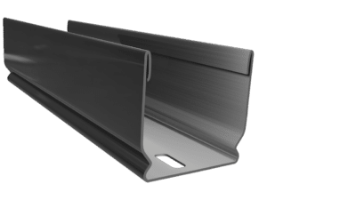
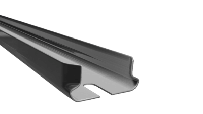
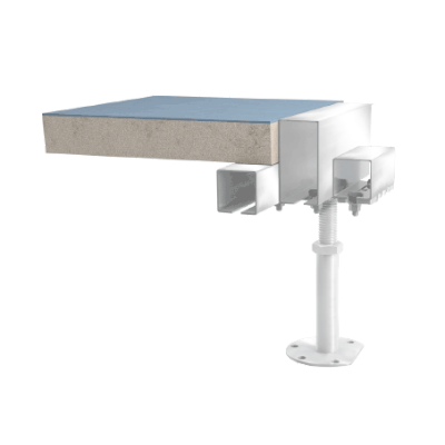
PEDESTALS with C-Profile
Pedestals with C-Profile from Weiss Raised floor systems
Also known as switchgear station floors, raised floor systems with C-profiles are used in rooms with electrical controlgear and switchgear, such as server rooms, control rooms and in areas requiring higher load carrying capacity.
The substructure comprises steel pedestals with height adjustment facility, which can be set to exactly the right height.
The substructure remains secure, even under heavy loads.
The transition from framework to walking area is on a level thanks to the connection of two different C-profiles.
This means that switchgear cabinets and other heavy items of equipment, such as transformers, UPS systems, battery cabinets and air conditioning units can be positioned on the C-profile framework directly.
This type of structure does not require any welding.
The bolted connection is permanently secured by means of hammer-head screws and it can be dismantled and used again several times without any detrimental effects on quality.
One of the major advantages of this type of construction is that it can be implemented quickly and the entire cross-section of the space under the switchgear cabinet is available for leading in cables.
Apart from this, the structure maintains its stability, even if the floor panels are open.
Related products


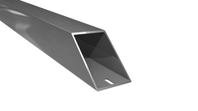
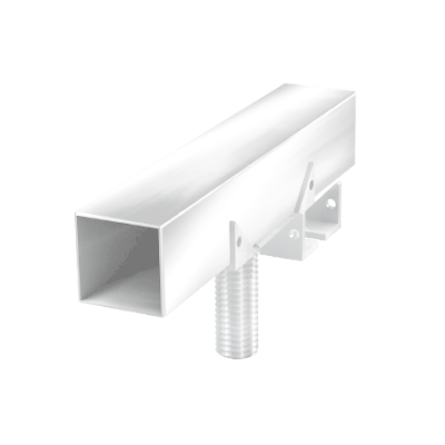
Pedestals with stringers
Pedestals with stringers von Weiss raised floor systems
Pedestals with stringers have steel cross braces, which are fitted into the prop heads of the underfloor construction and can also be bolted there.
The raised floor panels then rest on the sound-deadening pedestal pads and on the side faces.
This improves the horizontal rigidity of the complete underfloor construction, thereby increasing the load carrying capacity.
We recommend that stringers should be used to reinforce the substructure as a matter of principle for floor heights of 500 mm or more.
We offer various stringers to suit the respective system floor design
Product pictures
Product pictures